ME 3901 Engineering Experimentation
General information
“Laboratory 5: Vibrational Measurements”
Cell Phone Vibrations
via “Analog Devices: Single and Dual Axis Automotive iMEMS”
Note: These accelerometers were donated by Analog Devices
through the efforts of Professor Furlong.
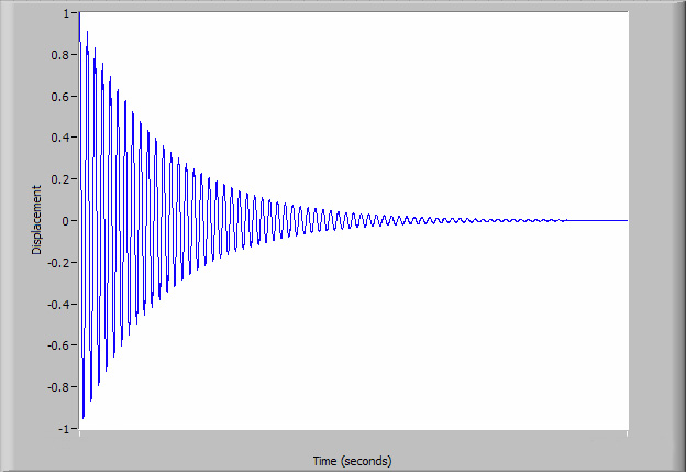
If the beam is deflected and then released, it will oscillate or vibrate, that is the deflection varies with time. It is a second-order system and can be described as periodic.
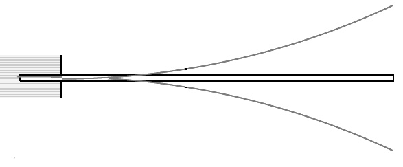
If a strain gage or accelerometer were attached to the beam it would generate a sinusoidal voltage output. The output amplitude would be proportional to the strain or acceleration and a period inversely proportional to the frequency of vibration. Left to vibrate freely, without applied external forces, the beam will vibrate at its natural frequency, ![]() , and its amplitude of the response will decrease with time, as energy in the system is lost.
, and its amplitude of the response will decrease with time, as energy in the system is lost.
The natural frequency can be quantified as:

where (![]() ) is the mass per unit length of the beam and Cn is a constant.
) is the mass per unit length of the beam and Cn is a constant.
Objective
The objective of this laboratory is to use a motion transducer (an accelerometer) to measure the frequency modes of your cell phone. Remember for this test, it is a forced vibration as opposed to a free vibration. Therefore, one should not see the exponential decay of the signal.
For each accelerometer test, vibration data will be analyzed to:
1. Determine the vibration amplitude, velocity, and acceleration in various units of measure;
2. Determine the cell phone frequency harmonics;
3. Compare measurement results as a function of transducer orientation (x vrs y frequency and magnitudes).
MEMS accelerometers
In this laboratory, the state-of-the-art Analog Devices ADXL276 dual-axes accelerometers will be utilized.
The ADXL276 MEMS accelerometer is currently being used in a wide range of consumer, industrial, military, and automotive applications.
The ADXL276 accelerometer has a measuring range of ±35 g (g = 9.81 m/s2) and it provides analog output signals with sensitivity on the order of 55 mV/g (for full source voltages).
The source voltage can range from 3 V to 5.25 V for operation and is capable of operating in a wide range of temperatures.
Tasks: MEMS accelerometers
Attach a small strip of mounting tape onto your phone.
Wire (solder – with safety glasses) the accelerometer tabs.
(The prongs are facing INTO the paper on the schematic below.)
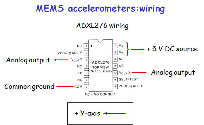
Attach the flat surface of the accelerometer to the mounting tape with the Y direction (Pins on right side to pins on left side)
aligned (parallel) with the short axis of the phone.
Connect the 5 V DC source to an analog ouput channel on the USB6229BNC unit.
Connect Pin 10 and Pin 7 (X voltage output + and -) to an analog input channel.
Connect Pin 3 and Pin 7 (Y voltage output + and -) to an analog input channel.
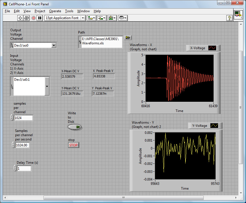
Create a LabView VI schematic to record time-frequency
data.
Try several sampling rates (128, 256, 512, 1024 samples per second)
Keep the number of samples the same as the sampling rate. In this mode
there should be approximately three rows of data written to file per
second (A time row, another row for the x-axis information, the third row for the y-axis).
A cantilever beam result (similar to a cell phone, but freely vibrating) is displayed below.
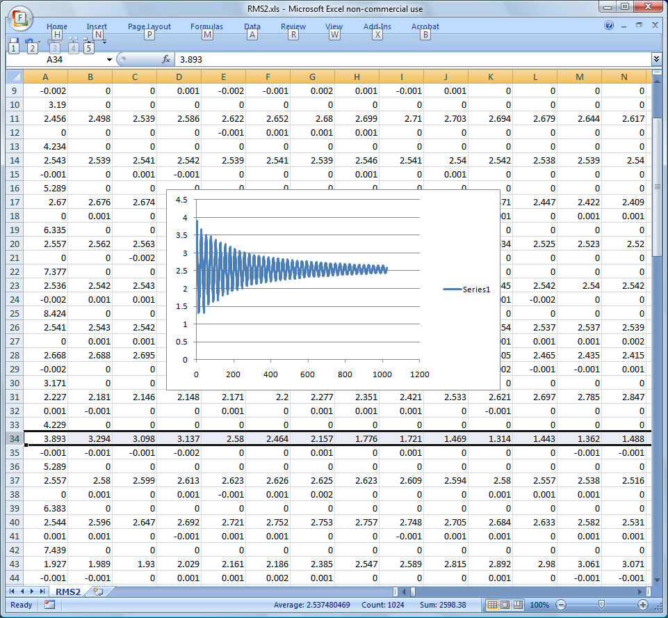
Using the recorded data (and your VI), determine frequency modes
of your phone.
What are the acceleration peaks of your phone?
Is there a difference in frequency, amplitude, etc. between to two measured axes?
For future reference, recall our formulations:
![]()
![]()
![]()
![]()